

How Does The Register Work In Assembly Language
Associates - Registers
Processor operations mostly involve processing data. This information tin can be stored in memory and accessed from thereon. However, reading data from and storing data into retentivity slows downwardly the processor, every bit it involves complicated processes of sending the data request across the control bus and into the retentiveness storage unit and getting the information through the same channel.
To speed up the processor operations, the processor includes some internal retention storage locations, called registers.
The registers store data elements for processing without having to admission the memory. A limited number of registers are congenital into the processor chip.
Processor Registers
There are ten 32-bit and six sixteen-scrap processor registers in IA-32 architecture. The registers are grouped into three categories −
- General registers,
- Control registers, and
- Segment registers.
The general registers are further divided into the following groups −
- Data registers,
- Pointer registers, and
- Alphabetize registers.
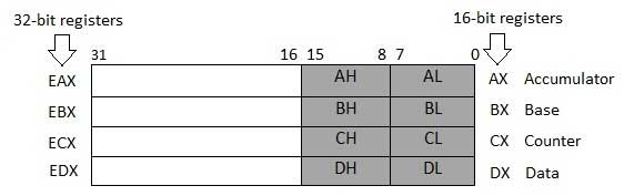
Data Registers
Four 32-fleck data registers are used for arithmetics, logical, and other operations. These 32-bit registers can be used in three ways −
-
As complete 32-bit data registers: EAX, EBX, ECX, EDX.
-
Lower halves of the 32-bit registers tin exist used as four 16-bit data registers: AX, BX, CX and DX.
-
Lower and college halves of the in a higher place-mentioned 4 16-bit registers can be used as 8 8-scrap data registers: AH, AL, BH, BL, CH, CL, DH, and DL.
Some of these data registers have specific utilize in arithmetical operations.
AX is the primary accumulator; it is used in input/output and most arithmetic instructions. For example, in multiplication functioning, one operand is stored in EAX or AX or AL annals according to the size of the operand.
BX is known as the base annals, as information technology could be used in indexed addressing.
CX is known as the count register, as the ECX, CX registers store the loop count in iterative operations.
DX is known as the data register. It is also used in input/output operations. It is also used with AX register along with DX for multiply and divide operations involving large values.
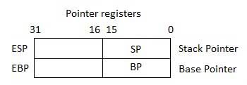
Pointer Registers
The pointer registers are 32-chip EIP, ESP, and EBP registers and respective 16-scrap right portions IP, SP, and BP. There are three categories of pointer registers −
-
Instruction Pointer (IP) − The xvi-bit IP annals stores the offset address of the adjacent instruction to be executed. IP in association with the CS register (as CS:IP) gives the complete accost of the current educational activity in the code segment.
-
Stack Pointer (SP) − The 16-bit SP register provides the offset value within the programme stack. SP in clan with the SS register (SS:SP) refers to be electric current position of information or address within the program stack.
-
Base Pointer (BP) − The 16-bit BP annals mainly helps in referencing the parameter variables passed to a subroutine. The address in SS register is combined with the offset in BP to get the location of the parameter. BP tin can also be combined with DI and SI as base of operations register for special addressing.
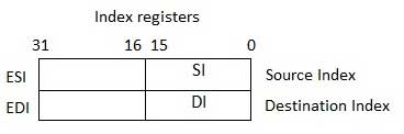
Index Registers
The 32-fleck index registers, ESI and EDI, and their 16-chip rightmost portions. SI and DI, are used for indexed addressing and sometimes used in addition and subtraction. There are ii sets of index pointers −
-
Source Alphabetize (SI) − Information technology is used every bit source index for string operations.
-
Destination Index (DI) − Information technology is used as destination index for string operations.
Control Registers
The 32-bit education pointer annals and the 32-bit flags register combined are considered every bit the control registers.
Many instructions involve comparisons and mathematical calculations and change the status of the flags and another provisional instructions test the value of these status flags to take the command catamenia to other location.
The common flag bits are:
-
Overflow Flag (OF) − It indicates the overflow of a loftier-society bit (leftmost bit) of information afterwards a signed arithmetic operation.
-
Direction Flag (DF) − Information technology determines left or right direction for moving or comparison cord data. When the DF value is 0, the string operation takes left-to-right management and when the value is prepare to 1, the string operation takes correct-to-left management.
-
Interrupt Flag (IF) − It determines whether the external interrupts like keyboard entry, etc., are to exist ignored or processed. It disables the external interrupt when the value is 0 and enables interrupts when set to 1.
-
Trap Flag (TF) − Information technology allows setting the operation of the processor in unmarried-pace mode. The DEBUG program nosotros used sets the trap flag, so we could step through the execution one didactics at a time.
-
Sign Flag (SF) − It shows the sign of the issue of an arithmetic operation. This flag is fix according to the sign of a information detail following the arithmetic operation. The sign is indicated by the high-social club of leftmost flake. A positive result clears the value of SF to 0 and negative effect sets it to i.
-
Zero Flag (ZF) − It indicates the result of an arithmetic or comparing operation. A nonzero event clears the zero flag to 0, and a zero event sets it to 1.
-
Auxiliary Comport Flag (AF) − Information technology contains the carry from bit 3 to bit 4 following an arithmetic functioning; used for specialized arithmetic. The AF is set when a ane-byte arithmetic operation causes a carry from chip iii into chip four.
-
Parity Flag (PF) − It indicates the total number of 1-$.25 in the result obtained from an arithmetic operation. An fifty-fifty number of i-bits clears the parity flag to 0 and an odd number of ane-bits sets the parity flag to i.
-
Bear Flag (CF) − It contains the carry of 0 or i from a loftier-order bit (leftmost) after an arithmetic performance. Information technology likewise stores the contents of terminal bit of a shift or rotate operation.
The post-obit table indicates the position of flag $.25 in the 16-fleck Flags annals:
| Flag: | O | D | I | T | S | Z | A | P | C | |||||||
|---|---|---|---|---|---|---|---|---|---|---|---|---|---|---|---|---|
| Bit no: | 15 | 14 | 13 | 12 | 11 | x | nine | eight | 7 | 6 | 5 | four | 3 | 2 | one | 0 |
Segment Registers
Segments are specific areas divers in a program for containing data, code and stack. At that place are three main segments −
-
Code Segment − It contains all the instructions to be executed. A 16-flake Code Segment register or CS register stores the starting accost of the lawmaking segment.
-
Data Segment − It contains data, constants and work areas. A 16-fleck Data Segment register or DS register stores the starting address of the information segment.
-
Stack Segment − Information technology contains information and return addresses of procedures or subroutines. It is implemented as a 'stack' information structure. The Stack Segment annals or SS annals stores the starting address of the stack.
Apart from the DS, CS and SS registers, in that location are other extra segment registers - ES (extra segment), FS and GS, which provide boosted segments for storing information.
In associates programming, a program needs to access the memory locations. All retentivity locations inside a segment are relative to the starting address of the segment. A segment begins in an address evenly divisible by sixteen or hexadecimal 10. And then, the rightmost hex digit in all such memory addresses is 0, which is not mostly stored in the segment registers.
The segment registers stores the starting addresses of a segment. To go the verbal location of data or instruction inside a segment, an offset value (or displacement) is required. To reference whatsoever retention location in a segment, the processor combines the segment accost in the segment annals with the get-go value of the location.
Example
Await at the post-obit simple program to understand the use of registers in assembly programming. This program displays 9 stars on the screen along with a simple message −
section .text global _start ;must be alleged for linker (gcc) _start: ;tell linker entry bespeak mov edx,len ;message length mov ecx,msg ;message to write mov ebx,1 ;file descriptor (stdout) mov eax,four ;system call number (sys_write) int 0x80 ;telephone call kernel mov edx,9 ;message length mov ecx,s2 ;message to write mov ebx,one ;file descriptor (stdout) mov eax,4 ;system telephone call number (sys_write) int 0x80 ;telephone call kernel mov eax,1 ;system call number (sys_exit) int 0x80 ;call kernel section .data msg db 'Displaying 9 stars',0xa ;a message len equ $ - msg ;length of bulletin s2 times 9 db '*'
When the above code is compiled and executed, it produces the following result −
Displaying 9 stars *********

How Does The Register Work In Assembly Language,
Source: https://www.tutorialspoint.com/assembly_programming/assembly_registers.htm
Posted by: smithappee1960.blogspot.com
0 Response to "How Does The Register Work In Assembly Language"
Post a Comment